TinyRenderer
Dec 16, 2024
10 mins read
1 画线
mainCRTStartup
void line(int x0, int y0, int x1, int y1, TGAImage& image, TGAColor color)
{
	for (float t = 0.f; t < 1; t += 0.01)
	{
		int x = x0 + (x1 - x0) * t;
		int y = y0 + (y1 - y0) * t;
		image.set(x, y, color);
	}
}
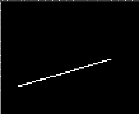
描绘了100个点,但是能否用x来遍历,这样可以从13 - 80 只需要描绘67个点
void line(int x0, int y0, int x1, int y1, TGAImage& image, TGAColor color)
{
	for (int x = x0; x < x1; x++)
	{
		float t = (x - x0) / (float)(x1 - x0);
		int y = y0 * (1 - t) + y1 * t;
		image.set(x, y, color);
	}
}
可行,需要注意整数除法。
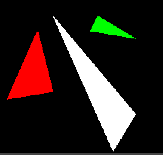
但是当增加两条线段时
line(13, 20, 80, 40, image, white);
line(20, 13, 40, 80, image, red);
line(80, 40, 13, 20, image, red);
Question:
-
实际上第一条线和第三条线是同一条线,为什么第三条线没有显示出来?
-
第二条线段是离散的点而不连续
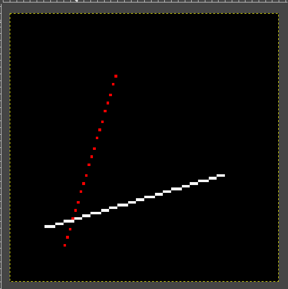
Answer:
- 我们的函数只处理了x1 > x0的情况
- 斜率增加,y增加的太快导致离散
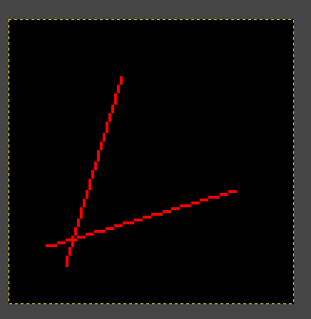
void line(int x0, int y0, int x1, int y1, TGAImage& image, TGAColor color)
{
	bool steep = false;
	if ((y1 - y0) / (x1 - x0) > 1)
	{
		// 关于 x = y对称
		std::swap(x0, y0);
		std::swap(x1, y1);
		steep = true;
	}
	if (x0 > x1)
	{
		std::swap(x0, x1);
		std::swap(y0, y1);
	}

	for (int x = x0; x < x1; x++)
	{
		float t = (x - x0) / (float)(x1 - x0);
		int y = y0 * (1 - t) + y1 * t;
		if (steep)
		{
			image.set(y, x, color);
		}
		else
		{
			image.set(x, y, color);
		}
	}
}
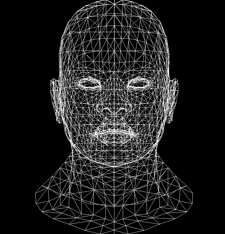
线框渲染
打开Obj文件以文本编辑器形式
v -0.000581696 -0.734665 -0.623267
v 0.000283538 -1 0.286843
v -0.117277 -0.973564 0.306907
...
# 1258 vertices

vt  0.532 0.923 0.000
vt  0.535 0.917 0.000
vt  0.542 0.923 0.000
...
# 1339 texture vertices

vn  0.001 0.482 -0.876
vn  -0.001 0.661 0.751
vn  0.136 0.595 0.792
...
# 1258 vertex normals

g head
s 1
f 24/1/24 25/2/25 26/3/26
f 24/1/24 26/3/26 23/4/23
f 28/5/28 29/6/29 30/7/30
...
# 2492 faces
Model.h文件
class Model {
private:
	std::vector<Vec3f> verts_;
	std::vector<std::vector<int> > faces_;
public:
	Model(const char *filename);
	~Model();
	int nverts();
	int nfaces();
	// 返回模型中的第i个顶点
	Vec3f vert(int i);
	//返回模型中的第idx个面 面由顶点索引构成
	std::vector<int> face(int idx);
};
main.cpp文件
for (int i=0; i<model->nfaces(); i++) {
    // 获取第i个面
    std::vector<int> face = model->face(i);
    // 遍历面上的点 三角形
    for (int j=0; j<3; j++) {
        // 获取两个点
        Vec3f v0 = model->vert(face[j]);
        Vec3f v1 = model->vert(face[(j+1)%3]);
        // 将坐标从[-1, 1]转换成屏幕坐标[0, width]
        int x0 = (v0.x+1.)*width/2.;
        int y0 = (v0.y+1.)*height/2.;
        int x1 = (v1.x+1.)*width/2.;
        int y1 = (v1.y+1.)*height/2.;
        line(x0, y0, x1, y1, image, white);
    }
}
其中视口变换将 标准化设备坐标(NDC) 转换为 屏幕坐标系。
加 1 的作用:
- 将 NDC 范围 [−1,1] 平移到 [0,2],这样负坐标就能变为非负值。
乘以 width/2和 height/2:
- 将归一化范围 [0,1] 放大到屏幕分辨率范围。
- width/2 和 height/2 是 NDC 范围 [0, 1] 到屏幕范围的比例因子。
2 画面
已经有了线框三角形,如何把三角形绘制出颜色?
可以使用一根根线绘制出三角形,就像是用一个个点绘制直线一样。将三角形从上至下分成一条条直线,通过遍历 Y,得到线的两个端点,再去绘制线在每个 Y 处。
由于三角形的不规则,所以必须要分为两部分,通过相似三角形,可以求出线的 X, Y 点。
逐行扫描填充法
void triangle(Vec2i t0, Vec2i t1, Vec2i t2, TGAImage& image, TGAColor color) {
    if (t0.y > t1.y) std::swap(t1, t0);
    if (t1.y > t2.y) std::swap(t2, t1);
    if (t0.y > t2.y) std::swap(t2, t0);
    if (t0.y == t1.y && t1.y == t2.y) return;

    int total_height = t2.y - t0.y;
    for (int y = 0; y < total_height; y++)
    {
        // 如果是上半部分 segment_height就为true 下半部分为false
        bool second_half = y > t1.y - t0.y || t1.y == t0.y;
        int segment_height = second_half ? t2.y - t1.y : t1.y - t0.y;

        // 表示扫描线位置在 t0 至 t2 的相对位置
        float alpha = (float)y / total_height;
        // 如果是上半部分,高度要减去下半部分的高度 如果是下半部分就直接是y
        float beta = (float)(y - (second_half ? t1.y - t0.y : 0)) / segment_height;

        // A是在三角形长线一侧 同一条长线中等比例求线段左边的坐标
        Vec2i A = t0 + (t2 - t0) * alpha;
        // B是在三角形分为上下部分的两条边一侧
        Vec2i B = second_half ? t1 + (t2 - t1) * beta : t0 + (t1 - t0) * beta;
        if (A.x > B.x) std::swap(A, B);
        for (int j = A.x; j <= B.x; j++)
        {
            image.set(j, t0.y + y, color);
        }
    }
}
重心坐标法
遍历三角形的包围盒中的所有像素,使用重心坐标法判断当前像素是否位于三角形内部。
包围盒算法(待实现)第 2 课:三角形栅格化和背面剔除 ·ssloy/tinyrenderer 维基
Vec3f barycentric(Vec2i *pts, Vec2i P) {
    Vec3f u = Vec3f(pts[2][0]-pts[0][0], pts[1][0]-pts[0][0], pts[0][0]-P[0])^Vec3f(pts[2][1]-pts[0][1], pts[1][1]-pts[0][1], pts[0][1]-P[1]);
    /* `pts` and `P` has integer value as coordinates
       so `abs(u[2])` < 1 means `u[2]` is 0, that means
       triangle is degenerate, in this case return something with negative coordinates */
    if (std::abs(u.z)<1) return Vec3f(-1,1,1);
    return Vec3f(1.f-(u.x+u.y)/u.z, u.y/u.z, u.x/u.z);
}

void triangle(Vec2i *pts, TGAImage &image, TGAColor color) {
    Vec2i bboxmin(image.get_width()-1,  image.get_height()-1);
    Vec2i bboxmax(0, 0);
    Vec2i clamp(image.get_width()-1, image.get_height()-1);
    for (int i=0; i<3; i++) {
        bboxmin.x = std::max(0, std::min(bboxmin.x, pts[i].x));
	bboxmin.y = std::max(0, std::min(bboxmin.y, pts[i].y));

	bboxmax.x = std::min(clamp.x, std::max(bboxmax.x, pts[i].x));
	bboxmax.y = std::min(clamp.y, std::max(bboxmax.y, pts[i].y));
    }
    Vec2i P;
    for (P.x=bboxmin.x; P.x<=bboxmax.x; P.x++) {
        for (P.y=bboxmin.y; P.y<=bboxmax.y; P.y++) {
            Vec3f bc_screen  = barycentric(pts, P);
            if (bc_screen.x<0 || bc_screen.y<0 || bc_screen.z<0) continue;
            image.set(P.x, P.y, color);
        }
    }
}
绘制模型的三角面
一开始发现整个模型都是白色,看不到任何面片,这是因为没有光照。
法向量与光照负方向夹角小于90°,被照亮;而虚线右边是背光的一侧,法向量与光照负方向夹角大于90°,处于黑暗中。(也就是背面裁剪)
for (int i = 0; i < model->nfaces(); i++)
{
    std::vector<int> face = model->face(i);
    Vec2i screen_coords[3];
    Vec3f world_coords[3];
    for (int j = 0; j < 3; j++)
    {
        Vec3f v = model->vert(face[j]);
        screen_coords[j] = Vec2i((v.x + 1.) * width / 2., (v.y + 1.) * height / 2.);
        world_coords[j] = v;
    }
    // 世界坐标点相减得出方向向量 两向量的叉积就是法线向量
    Vec3f n = (world_coords[2] - world_coords[0]) ^ (world_coords[1] - world_coords[0]);
    // 归一化 变成单位向量
    n.normalize();
    float intensity = n * light_dir;
    // 点乘 > 0 代表向光 点乘 < 0 代表背光 呢么就不渲染
    if (intensity > 0)
    {
        triangle(screen_coords[0], screen_coords[1], screen_coords[2], image, TGAColor(intensity * 255, intensity * 255, intensity * 255, 255));
    }
}
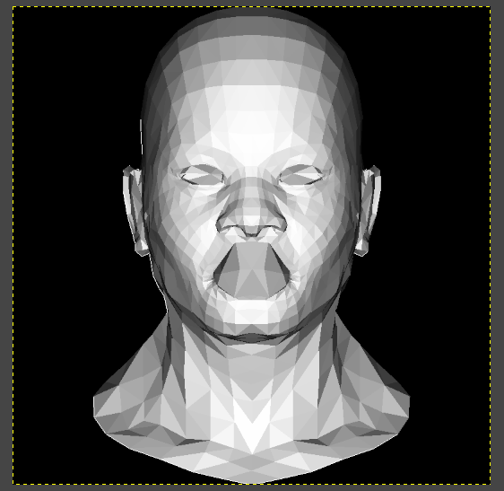
但是出现了问题:模型有一些地方比较奇怪,嘴巴部分。为什么会出现这样的情况?因为模型有一些内部的面覆盖了外面的面,所以引出来了ZBuffer。
Sharing is caring!